Showing posts with label sweet sister. Show all posts

24 October 2014

U-bolt installation

September 2014


This was done two seasons ago and I don't think I ever posted pics.

At Cherubini we used to have heavy stainless-steel chainplates fabricated for the C44s. About five years ago a customer wanted these replaced and we sent out for a quote, getting a figure of about $125 for each one. There are ten rigging-attachment points on each side of a Cherubini 44.

In about 1980 Lee and I did some research, really just as an intellectual exercise, and discovered that common type-316 stainless-steel U-bolts, such as are used for transom tie-down points on trailerable boats, are both phenomenally strong and amazingly cheap. Therefore we concluded by revising the engineering specification for new C44 construction that we'd use Attwood 1/2" U-bolts for the main shrouds and 3/8" ones for the mizzens. These are rated at 16,000 and 12,000 lbs breaking load, respectively. So any four of them would serve as harness-attachment points to lift the whole boat. These were bolted through that massive solid-fiberglass flange, for which the C44 is famous (see Ferenc Mate's books) and reinforced with a 2" x 2" stainless-steel angle about six feet long. This has never, not once, ever failed in any C44 or C48, despite boats' having been subjected to incalcuable stresses due to storms and other conditions.

Meanwhile Hunter continued building boats with problematic through-deck chainplates bolted to plywood bulkheads that were treated with, if anything, polyester resin. Now how many of these boats' structures have failed?

I was resolved, from the start, to replace Diana's pokey little above-deck shroud-attachment angles with U-bolts.

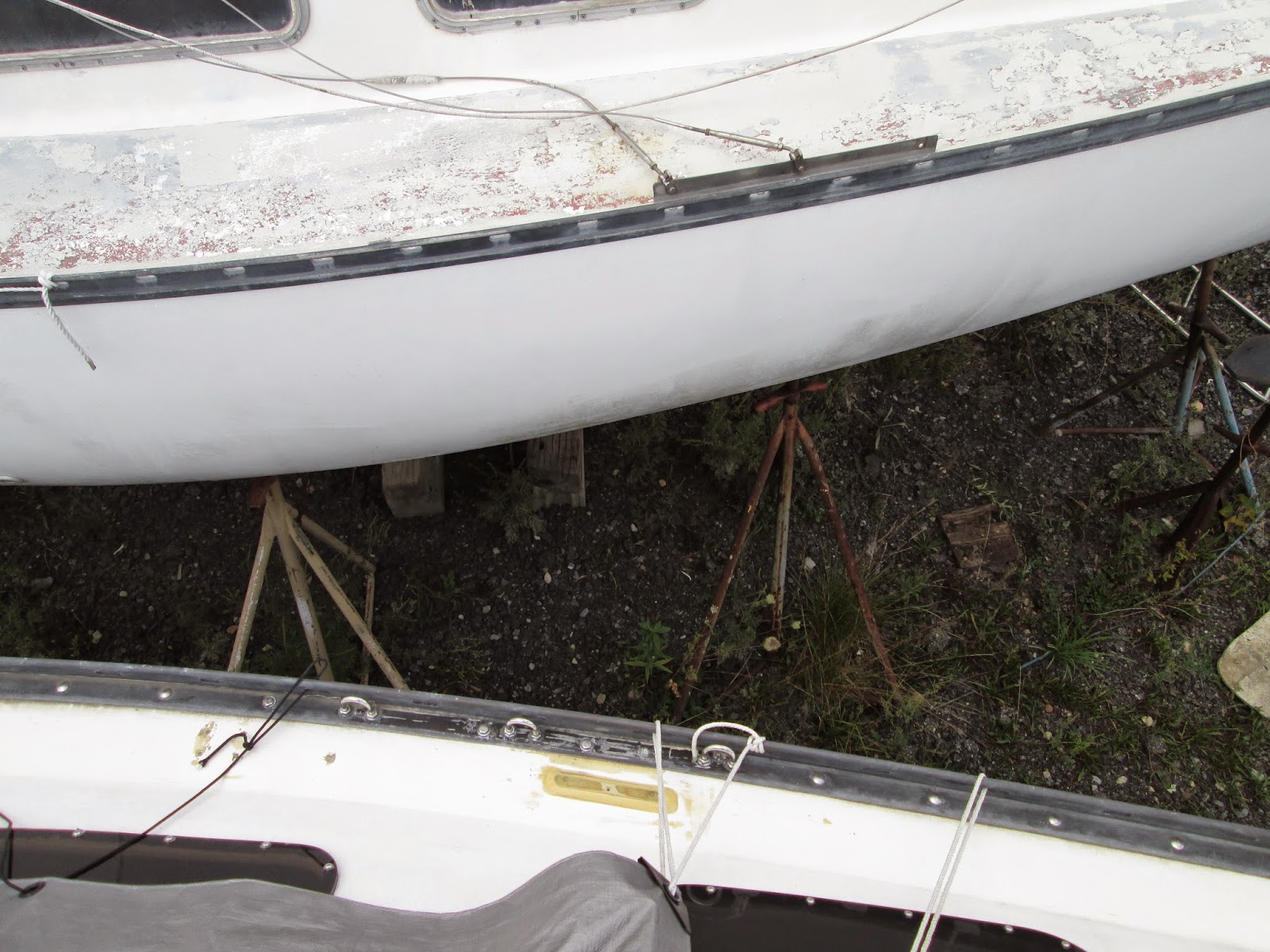
Below is a pic from the cabintop comparing Diana's U-bolts (below) and the original factory 'chainplates' (above, on her sistership). The plate on Diana's deck is a G-10 bolster (riser) epoxied to the fiberglass to serve as a base plate for the stanchion base. The vintage Schaefer stanchion base will span the gap, having two bolts through the plate and two through the toerail (one of which replaces one of the existing toerail bolts). In this way water can travel past (under) it, rather than pooling on top of it and working its way (such as with the help of ice) into the boltholes. I am not too keen on having a stanchion located between chainplate-attachment points; but it's only for lifelines and we'll see how it turns out.


There is tape residue about Diana's toerail in this picture. Wherever there was aluminum corrosion, from under the SS plate, against the rail, I scraped away the softened material and coated it in black 5200. There's nothing else for it but to remove the entire toerail; and I'm not ready to go there (kind of like insisting on an unnecessary operation for a child who can very easily live comfortably with the malady's symptoms for many years yet). Note that these U-bolts are very close to the vertical face of the toerail. Attaching the shrouds will be problematic unless done by screwing the bottles onto the toggles already pinned to the U-bolts. But, again, we'll see. 

The first photo shows, from below, the starboard-side aluminum angle with the U-bolt bolted through it. All of these stainless-to-aluminum connections employ nylon flat washers and plenty of 5200. Note that the angle is turned with the vertical face inboard, not outboard against the hull. The locknuts are accessible from below and inside the aluminum angle. This piece of metal is about 1" wide and about 1-1/4" high. Keep in mind that its job is to enforce stiffness of the chainplate structure (against fatiguing flexing) as well as to serve as a backing plate (against tensile loads). Therefore the longer leg of the aluminum is vertical, not flat against the flange.


The big orange wire is my 115VAC system. When we had our Raider 33 (hull 5, about 1977) built, my dad paid a guy about $1200 to do the wiring (since he hated wiring) and the result was stiff, balky, marine-grade 12/3 triplex wire that was heavy and impossible to get to yield if it got in your way. My dad (typically curbing the compulsion to curse, to which anyone else would have given in) said, 'I'd been happier with an extension cord thrown through the window.' Recalling this, when it came time to wire Diana for 115VAC, I got a decent 14/3 extension cord from Lowe's and cut it into pieces for Diana's three sockets and battery charger. I mean, really-- it's only 15-amp service anyway. (In the yard, currently, I run everything-- except the heat gun and fan together-- on a similar wire. The power inlet is for 30 amps but the cord has a plug for 15-amp sockets on the dock.) 

The silver wire is the sending circuit for the depth finder. Note the 1974-vintage woven roving (trade name 'Fabmat') of the hull, even this high up. I'm embarrassed by this next pic because apparently I missed a spot when spraying in the adhesive for the hull liner.

This is Diana's port-side U-bolts angle, inside the linen cupboard in the head. Here is where I ran all the wiring-- the reds and yellows in this picture are all heading forward from the head for bow-rail bi-color light, (LED) floodlights in the forepeak, and one cabin light (an original one I rejuvenated) to be mounted on the bulkhead.

The white wire is for LED footlights along the bottoms of cabinetry and bunkfronts. That's three reds and a white. The black and heavier white one (VHF coax) are leading from the mast step towards the panel, aft.


The fourth red is for a secret: with the hull-mounted bow lights removed, Diana will be getting blue-LED 'eyes' in these openings, lending her personality-- but I'm not advertising that and it'll be something to be shown off at the commissioning party!


The Sweet Sister


The sistership, one of the trunk-cabin model I call 'series 2', beside Diana is destined to become as much a celebrity as Diana is (rather like Haylie Duff or Beth Ringwald). I have been calling her 'The Sweet Sister' as, though she is within two weeks of Diana's age, she has been terribly neglected and yet remains in better condition than Diana was when I acquired her and brought here. (For example, the deck and cabintop are all solid. She has not had the distress of having had POs screwing down hardware without proper preparation.)


The current owner has only recently acquiesced to my interest in gaining her title; and over the winter and spring I will be performing a basic restoration of her, topsides, interior, and rig, incorporating several Diana features but otherwise letting her remain stock, as a kind of comparison to my (highly-modified) boat. Of course the sister will be getting U-bolts, my mast step, a 115VAC system, stanchion-base bolsters and the same color scheme as Diana's.

Look for her at the planned Hunter Sail-In in Burlington NJ in early July-- she'll be up for sale (but only to a good home).


* * *

24 May 2014

Diana's new stemhead fitting

I never liked the three-legged Hunter 25 pulpit and meant to replace it with something cooler from the very start.  This would mean cutting off the 7/8" stainless-steel stud from the stemhead fitting and polishing it over; but as Diana's PO had put her into some kind of close encounter with a piling, the original stemhead fitting was quite mangled and badly restraightened.  So I determined to make a new one.

I designed a very nice replacement part for this but found no one to make it at a reasonable price.  Then I happened to stumble across one on the Racelite web page and ordered it.  Though the dimensions on the site represented an adequate part, the actual thing seemed to represent them only nominally-- the thickness was not a true 1/8" and the length was entirely too short.  Rather typically I sat on this problem for over a year, working on other things, while I contemplated some solution.

Finally I ordered some flat stock, cut it to length, and sent it out to the local welders' with a pattern of the correct angle.  The part I received was simply beautiful.  I have begun to polish it and will finish it off before it's permanently installed.


You can see how the original part was only about 60 percent as long as it needed to be along the stem.  The flat stock welded to the part effectively doubles the thickness for the first three holes.  It is true that the tang for the forestay is still of the thin (original) stock; but as it's already thicker than were the shroud tangs I'll install it as it is and see if, as the rig is tuned, I get any elongation of the hole.  If that will be the case (which I doubt) I'll have it remedied with more welding.  As this Racelite part is meant for 20-to'22-footers, and as it's already meant to carry the load of 1/4" clevis pins, I'm betting it won't ever be a problem.


In this pic I have set the part on the bow to check the fit.  Thanks to my template the welder's work resulted in a perfect fit. You will see the gap behind the very top of the fitting-- this requires attention.  If I were to mount this as-is, two things would happen: Diana's J measurement (foot of the headsail) would be longer than that of a stock Hunter 25 by about 7/8"; and the natural stresses of a tuned and ruggedly-used rig would attempt to bend the fitting aftwards, putting the single screw through the deck into a shear load, and some distortion would occur.  This is why it is never wise to suspend rigging attachments over air, as would be done here.  I will fabricate a little block for in this gap, just something to support the compression load, and 'glass or epoxy it into place prior to paint and prior to attaching this fitting.

The horizontal pencil lines are marking where the mounting holes will go.  Only one of the original holes lined up.  I have a mahogany backing block for this, to be bedded in 5200 inside, and will drill new holes for the 1/4-20 hex-head cap screws.  Hex-heads are best for this sort of thing because you can put a ratchet and socket on each one and really tune them well.  Large-scale Phillips and, worse, slotted-head screws are really kind of pointless after a while.  A larger screw implies a larger load which means installation torque matters more.  No one can apply appropriate torque with a screwdriver handle.  I think the only reason people dislike hex-headed cap screws is because they make the boat look like Frankenstein's monster.  Personally, I like the look.  It's its own aesthetic.

The evident damage to the bow was from the PO.  The starboard-side toerail was cut to facilitate the fiberglass repair and reattached.  Coincidentally, this piece will have to be cut down to accommodate the anchor roller.  I'll fill the seam in the toerail with black 4000-UV to minimize the appearance of a crack.  Much of the old fiberglass repair was faired over with 3M filler (the grayer stuff).  The darker brown-olive is raw fiberglass from my sanding.  I have filled all the imperfections with both Evercoat 27 and epoxy and after painting with epoxy paint (Perfection or Brightside) this won't be visible or vulnerable.

The brown thing above the deck is the work-order tag from the welders'.  Mistakenly they wrote it up as being for my cousin Dave's shop; but this was my project and I contracted and paid for it.  (This happens a lot, actually.)

Sales pitch #1

If any other H25 owner is interested in having one of these parts, I will be happy to supply it.  It does, however, require a 4-legged pulpit; though I'd consider that an improvement.  I've designed an updated bow rail for Diana, along the lines of a J27's, complete with step-through end, varnished-mahogany seat/step with nonskid, and mount for Aqua Signal running light; though I'll be installing a plain-Jane castoff pulpit from another boat for the short term.

Sales pitch #2

Yes; the boat beside Diana, evident in one of these pics, is one of her sisters-- in this case a fellow February 1974 boat, this one the later trunk cabin/pop-top model.  They are both of the same series, Diana being number 027 and the other boat being 140.  At that time Hunter had two production lines of H25s at their Marlboro, New Jersey, plant; and I believe that the "0" signified the period's production series of "blister-canopy" or "flush-deck" models and the "1" signified the trunk-cabin models. If these boats were not on the production floor at the same time, they are probably not more than two weeks apart in age.

I have been referring to this other boat as "the sweet sister" and  hope to enter negotiations with her owner to take over her care and to restore her-- for she is still, even with an inadequate cover, in better condition than Diana was when I first found her and would represent a pretty easy, quick and profitable "quick fix" and resale.  She'll need some deck-core repair, paint, new cushions and upholstery, lifelines and probably cordage; and I do not know if there is an engine available.  But it wouldn't take much more than that for her to go sailing again.  As soon as Diana goes in I will have this boat shrink-wrapped and set a dehumidifier in her, to help preserve her.  Anyone interested is welcome to get in touch.

* * *