Showing posts with label aluminum. Show all posts

15 November 2014

Moving day

24 October 2014


I have not been happy with the boat's being where it's been.  This is sort of the 'swamp' of the yard.  Well-- it is not really a swamp-- Diana has been sitting on good solid packed gravel-- but the ground immediately beside her is low and tends to fill up in any rain.  This, in addition to the constant mosquitoes, makes doing boat work after 4.00 pm and on weekends less than fun.  So I contracted the guys to relocate Diana to a drier, happier place, especially with regards to facing another (her last?) winter on land.

Here in the Northeast, when placing a boat for the winter season, it is best to situate her nose-into the weather.  This is better for the boat, for any covers, for the stowage of gear on deck and on the ground, for persons entering the boat in the off-season, and for a host of a million other reasons.  Diana, especially, with her low-profile deck and cabin, heads to weather very well-- but all my covers and the cockpit have taken a beating over these (too many) years sitting stern-to the weather, which here in Delran comes to us on a direct line from Philadelphia (bearing from W/SW) in summer and from W and NW in winter.  The compass in the bulkhead shows her facing E/SE.  Enough said.


This is Diana's old spot, in 'The Swamp'.  Here Jerry's C44 Second Alarm has been moved to his new spot and I was standing, for the first time in two years, where his boat had been.  Together these boats and the others in this photo weathered Superstorm Sandy and all the rest.


Now I know how these guys work.  The guys from Riverside Marina come over, back the hydraulic boat carrier to the front of your boat, and then-- wait for it-- remove all the stands.  I mean all of them but the very back and the very bow.  I've seen them do this even on windy days, with the rig up.  Yikes.

Watching them do this with a C44 or Ben's Rhodes Reliant (with that narrow transom!) is unnerving.  Watching them do it with my own boat is an automatic case of the heebie-jeebies.  I was so paranoid that I subtly replaced the stands in the very back with a pair a little closer forward, though they were not at any bulkhead, just to persuade them to leave those as the last two.  But they moved them back (to right where they were before), saying they couldn't get the truck under it.  I was near fits.


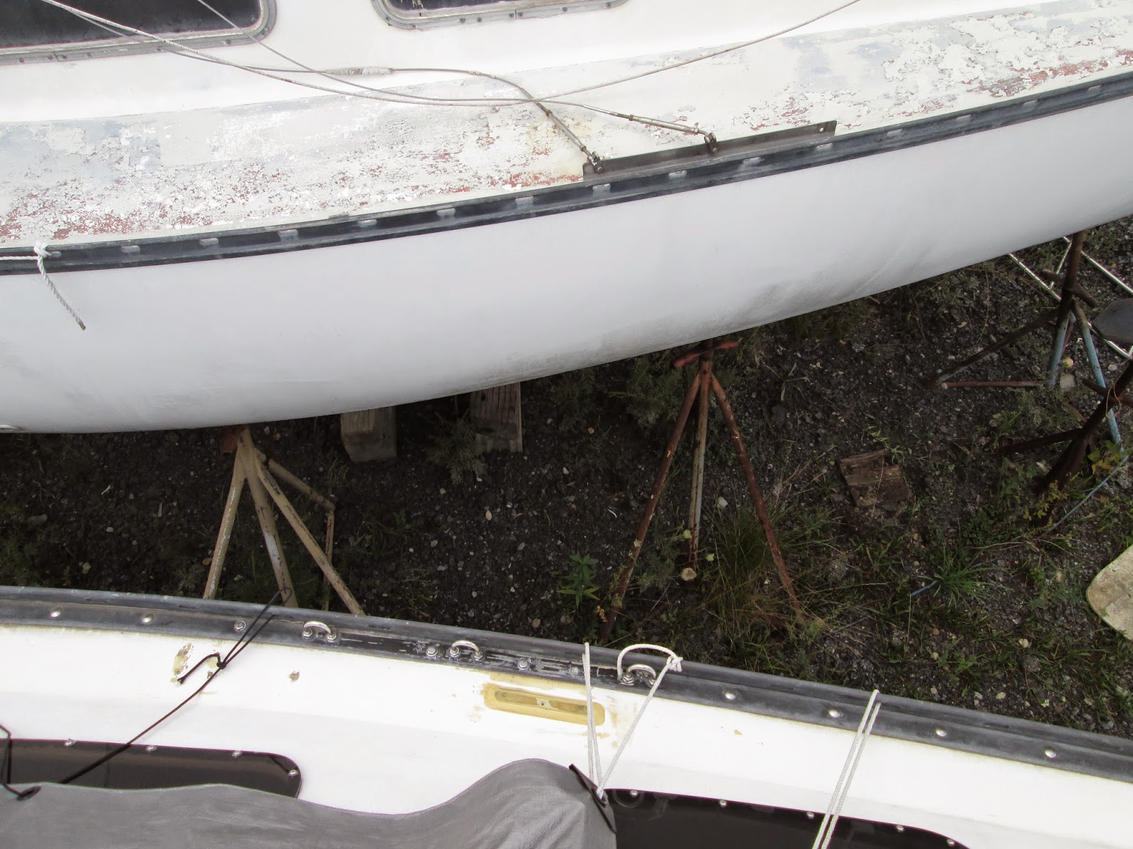
Then, to really bring on the stomach acid, the forward pads on the truck would not find the boat.  I've seen this thing in action many times but always thought that for smaller boats the pads would angle inwards.  Apparently, they don't.  The picture shows the back ones too far forward and too low, the front ones way too high, and the keel (read that: whole weight of the boat) on a 3-inch-wide strap spanned between the wheels of the truck thing.  Sheesh.

Meanwhile, between snapping photos (which I did not really do so much) I was worrying that the pads in front are pushing against the v-berth shelf, probably popping off the rode-locker bulkheads I 'glassed there, and definitely scraping off the newly-applied primer paint.

Then Jeremiah in the shop says, 'It better not be scraping off the paint.  It's epoxy.  If they're scraping it off, it wasn't applied right.'  And it was applied right.

End result: Diana arrives across the yard safe and sound.  There was a problem with blocking her, as the guys could not get the strap out from under the keel without blocking the keel bottom in the same place as before-- meaning I still can't scrape, prime and barrier-coat the very bottom.  But I can sort that out another day.  The bulkheads forward were fine (of course).  And the epoxy primer survived very well-- the traces of black wiped off with one hand while I was talking on the phone.  No worries.


In this location the barn part of the shop will block most wet snow.  The weather now comes from off Diana's nose or from slightly to port.  I will have this shrink-wrapped by the end of November (after topcoat on the hull).

The few odd places where the barrier coating was sanded through are the repairs I had to make for the cracks; this is reported elsewhere.  Jerry gave me some leftover stuff so I may not need to go into the quart kit of Pettit Protect that I bought for these (and for the rudder).  The gray cover is because of the instrument holes in the back of the cabin and because the forward edge of the hatch hood is still open (needing woodwork, the last major job to be done to the deck).

On the deck there is a bucket upside-down over the mast step.  The step will be removed for the deck to be painted and then reinstalled with 5200.

The holes forward, where the running lights were mounted, are to be covered with Plexiglas panels, as Diana's eyes (more on this 'secret' later). 

The foredeck hatch is slid open in this picture.  I have to put hinges on it, then remove them, then varnish the whole thing, which, with the boat under shrink-wrap, can easily be done in the shop.


Little Diana likes her new spot in the sun!


In the background can be seen the CY spars rack, welded and bolted to the side of the former storage trailer that is now the lumber-storage room for the shop.  On this rack are C44 spars, the ones for Dave's Reliant, and a few others.  Jeremiah puts each up there with the forklift (another operation that has to be seen to be believed).

I prefer six stands, not four (not counting the bow) because it's simple to pull one down to paint the bare spot.  The plywood steps came over from Diana's old place because I used them to fill and fair the old bow damage and will use them now to reinstall the section of toerail, the stem fitting and the anchor roller.  In this photo I have not yet moved the spars and the workbench to the new spot.

The half-gallon of iced tea is Turkey Hill from 7-11-- the very best cold green tea you can get!  :)

* * *

24 October 2014

U-bolt installation

September 2014


This was done two seasons ago and I don't think I ever posted pics.

At Cherubini we used to have heavy stainless-steel chainplates fabricated for the C44s. About five years ago a customer wanted these replaced and we sent out for a quote, getting a figure of about $125 for each one. There are ten rigging-attachment points on each side of a Cherubini 44.

In about 1980 Lee and I did some research, really just as an intellectual exercise, and discovered that common type-316 stainless-steel U-bolts, such as are used for transom tie-down points on trailerable boats, are both phenomenally strong and amazingly cheap. Therefore we concluded by revising the engineering specification for new C44 construction that we'd use Attwood 1/2" U-bolts for the main shrouds and 3/8" ones for the mizzens. These are rated at 16,000 and 12,000 lbs breaking load, respectively. So any four of them would serve as harness-attachment points to lift the whole boat. These were bolted through that massive solid-fiberglass flange, for which the C44 is famous (see Ferenc Mate's books) and reinforced with a 2" x 2" stainless-steel angle about six feet long. This has never, not once, ever failed in any C44 or C48, despite boats' having been subjected to incalcuable stresses due to storms and other conditions.

Meanwhile Hunter continued building boats with problematic through-deck chainplates bolted to plywood bulkheads that were treated with, if anything, polyester resin. Now how many of these boats' structures have failed?

I was resolved, from the start, to replace Diana's pokey little above-deck shroud-attachment angles with U-bolts.

Below is a pic from the cabintop comparing Diana's U-bolts (below) and the original factory 'chainplates' (above, on her sistership). The plate on Diana's deck is a G-10 bolster (riser) epoxied to the fiberglass to serve as a base plate for the stanchion base. The vintage Schaefer stanchion base will span the gap, having two bolts through the plate and two through the toerail (one of which replaces one of the existing toerail bolts). In this way water can travel past (under) it, rather than pooling on top of it and working its way (such as with the help of ice) into the boltholes. I am not too keen on having a stanchion located between chainplate-attachment points; but it's only for lifelines and we'll see how it turns out.


There is tape residue about Diana's toerail in this picture. Wherever there was aluminum corrosion, from under the SS plate, against the rail, I scraped away the softened material and coated it in black 5200. There's nothing else for it but to remove the entire toerail; and I'm not ready to go there (kind of like insisting on an unnecessary operation for a child who can very easily live comfortably with the malady's symptoms for many years yet). Note that these U-bolts are very close to the vertical face of the toerail. Attaching the shrouds will be problematic unless done by screwing the bottles onto the toggles already pinned to the U-bolts. But, again, we'll see. 

The first photo shows, from below, the starboard-side aluminum angle with the U-bolt bolted through it. All of these stainless-to-aluminum connections employ nylon flat washers and plenty of 5200. Note that the angle is turned with the vertical face inboard, not outboard against the hull. The locknuts are accessible from below and inside the aluminum angle. This piece of metal is about 1" wide and about 1-1/4" high. Keep in mind that its job is to enforce stiffness of the chainplate structure (against fatiguing flexing) as well as to serve as a backing plate (against tensile loads). Therefore the longer leg of the aluminum is vertical, not flat against the flange.


The big orange wire is my 115VAC system. When we had our Raider 33 (hull 5, about 1977) built, my dad paid a guy about $1200 to do the wiring (since he hated wiring) and the result was stiff, balky, marine-grade 12/3 triplex wire that was heavy and impossible to get to yield if it got in your way. My dad (typically curbing the compulsion to curse, to which anyone else would have given in) said, 'I'd been happier with an extension cord thrown through the window.' Recalling this, when it came time to wire Diana for 115VAC, I got a decent 14/3 extension cord from Lowe's and cut it into pieces for Diana's three sockets and battery charger. I mean, really-- it's only 15-amp service anyway. (In the yard, currently, I run everything-- except the heat gun and fan together-- on a similar wire. The power inlet is for 30 amps but the cord has a plug for 15-amp sockets on the dock.) 

The silver wire is the sending circuit for the depth finder. Note the 1974-vintage woven roving (trade name 'Fabmat') of the hull, even this high up. I'm embarrassed by this next pic because apparently I missed a spot when spraying in the adhesive for the hull liner.

This is Diana's port-side U-bolts angle, inside the linen cupboard in the head. Here is where I ran all the wiring-- the reds and yellows in this picture are all heading forward from the head for bow-rail bi-color light, (LED) floodlights in the forepeak, and one cabin light (an original one I rejuvenated) to be mounted on the bulkhead.

The white wire is for LED footlights along the bottoms of cabinetry and bunkfronts. That's three reds and a white. The black and heavier white one (VHF coax) are leading from the mast step towards the panel, aft.


The fourth red is for a secret: with the hull-mounted bow lights removed, Diana will be getting blue-LED 'eyes' in these openings, lending her personality-- but I'm not advertising that and it'll be something to be shown off at the commissioning party!


The Sweet Sister


The sistership, one of the trunk-cabin model I call 'series 2', beside Diana is destined to become as much a celebrity as Diana is (rather like Haylie Duff or Beth Ringwald). I have been calling her 'The Sweet Sister' as, though she is within two weeks of Diana's age, she has been terribly neglected and yet remains in better condition than Diana was when I acquired her and brought here. (For example, the deck and cabintop are all solid. She has not had the distress of having had POs screwing down hardware without proper preparation.)


The current owner has only recently acquiesced to my interest in gaining her title; and over the winter and spring I will be performing a basic restoration of her, topsides, interior, and rig, incorporating several Diana features but otherwise letting her remain stock, as a kind of comparison to my (highly-modified) boat. Of course the sister will be getting U-bolts, my mast step, a 115VAC system, stanchion-base bolsters and the same color scheme as Diana's.

Look for her at the planned Hunter Sail-In in Burlington NJ in early July-- she'll be up for sale (but only to a good home).


* * *

25 August 2012

Removing holes from aluminum spars

One vital consideration concerning aluminum spars is that they derive all their strength from skin stiffness.  Aluminum can and will bend; but as the molecules shift about it's important to not give them anywhere to go that they should not be.  This means all extra holes in an aluminum spar will weaken it.

My boat came with the then-common 1970s slab-reefing system consisting of a genoa track mounted on the boom, a cheek block mounted on a slide, and a Cunningham hook above the gooseneck.  The single-line reefing system as depicted in the Schaefer catalogue and elsewhere makes infinitely more sense, not only for sail trim but for simplicity and even safety.  Properly located, the parts of single-line reefing will contribute to a very efficient sail shape for the reefed sail and give one the ability to effect the reef from only one place-- in my boat's case, the safety of the bridge deck and main hatch.

To remove the parts of the old system required the filling of some two dozen holes on the boom and elsewhere.  Certainly one could weld these and have an excellent-- though expensive-- reconditioned boom.  Honestly I never thought of that; but I knew I'd have to fill them somehow.

Then Jeremiah, in the shop, suggested just using aluminum screws, threading them into the holes, and breaking them off to file them smooth.  The sheer simplicity of this idea just blew me away.  After all, so long as the holes are filled with something that can't shift-- thus prohibiting the molecules from moving too far-- it does not matter how you fill them.

Amazing Grace, the C48, came into the shop for a refit and I got the job of preparing the booms for refinishing.  As part of the job the aluminum screws were ordered; as soon as the necessary holes were filled I took off with the broken-off bolts and reused them all on my own boat. After all they only need to be long enough to thread into the wall thickness of the spar.


This first photo is not great, owing to glare; but the aluminum screws sticking out of the side of the boom (spar to the left) are visible. Most of these were for the reefing track.

The black tape marks where the sheetline bail will go.


In this photo you can see where a few of the screws have already been broken off.  I sawed most of the way through each one and then bent them with pliers to snap them off.  These screws are 1/4-20 thread.  They can break off when you're about 2/3 through them with the hacksaw.  The best idea is to saw them as close as possible to the surface of the spar-- but you'll have to choose one thread of the screw as the hacksaw blade will choose one for you otherwise.
The red stuff is Loctite 'permanent' (not my blood; that's elsewhere).  A caveat: the Loctite will work only if the hole is the right size for the screw and decently threaded.  Don't count on the Loctite to fill gaps (or even to stick if there are gaps).  If there is too much play, you can use epoxy (perhaps with a little filling compound) instead.


Here is the side of the boom after the screws were broken off and sanded over.  Can you see where they were? --for you certainly can't feel where they were with your hand.


Here is a close-up of the side of the boom, with a better view of the filled-in screw holes (silver circles).  I sanded these by hand-- 80-grit production paper takes the nubs down quickly and easily.  You will see a trace of greasy-looking aluminum residue following your sanding-- this tells you that you are actually sanding the end of the screw.  When you see the surface of the boom going silver you've come to the end (as you see how I hit it here).

I changed to 120 grit and then to 220 to polish these off.  As I will shortly be applying etcher, primer and paint I'll be able to further fair these places, should they need it, at any point during the future stages.


I filled the holes for the winch bases on the mast as well.  Since those holes were a bit too big to accommodate 10-24s any more, I drilled them all out to 1/4-20 (I should have used 12-24 but didn't think of it!).  In installing the winch bases on the mast again, to avoid running afoul of the old (now filled) holes, I can relocate them.  The open holes shown here are the new ones drilled to reuse the old mast bases in new locations.

(The pole in the back is the fence, not the spreaders!)


* * *


24 August 2012

Internal pole lift

Since this boat is so small, it's unlikely I'll ever have a proper whole-cockpit awning without setting it over the mainsail cover.  So when in the ICW or anywhere that calls for more powering than sailing, I won't have the opportunity to set any sail to assist the motor other than the jib itself, which is too far forward to allow the boat to balance under the one sail alone.  What's needed is a smaller sail more centrally set, fore-and-aft, that can pull reasonably well on most points of sail in light air... like an inner forestaysail.  And, more importantly, it will also serve to take over when/if the motor fails.

This is more important than most people realize.  A prudent mariner should never enter a dodgy or unfamiliar harbor with the mainsail cover drawn and snapped closed and the headsail bagged or lashed to the deck.  (I know-- most people will claim that having a roller-furling headsail resolves this.  But the point still bears consideration.)  In such a state, if you were to suffer an engine failure you'd be hard-pressed to get anything up and drawing air before you crashed or went aground.  It's a matter of simple seamanship.

I've had the idea to have a regular spinnaker-pole lift that can also be used as a halyard for a small jib, what I call the 'canal sail', something small but useful to assist the motor, provide safety and redundancy and maintain steerage in freaky currents and conditions.  I decided to use the former winch mount on the starboard side of the mast and to reuse the old Seaboard halyard winch for this.  (The port side gets another winch base and a Lewmar #6; more on this later).


This exit block came from DAMCO (Dwyer Aluminum Mast CO.)  These people are the very best in the business, helpful, sensible and economical.  This block cost $26.00 and handles 5/16" line (actually 3/8" would fit but oughtn't be loaded to capacity).  A Schaefer one is over $90.00.  I cut this hole and mounted this thing using tapped 10-24 screws; it will get removed when it comes time for paint and then reinstalled.

I calculated the location using an original 1973 blueprint of this boat's sail plan which Skip Moorhouse, sailmaker and first owner of Hunter 25 hull no. 1, let me inspect.  Assuming a theoretical inner forestay about 3'9" aft of the headstay, it would land on the foredeck about 4' aft of the headstay plate.  So the place for this block is about 9'7" down from the top of the mast.  In this way I could, if I chose to, fit a tang here to accommodate an inner forestay and running backstays and so configure this little boat as a bona-fide cutter.  I just figure if you're going to install something like this, you might as well make some sense of it, if only in theory.

At the other end I have to add an exit plate on the starboard side, rather high up in order ti lead it down to the winch.  The existing two exit plates are for the two main halyards.

In reusing the old Seaboard winch I have to keep in mind that the handle for it is a hexagonal drive, unlike modern standard square-drive winches.  Apparently in the early days of top-action winches (about 1968-1978), there was no standard top-drive handle format (sounds eerily familiar to the development patterns of other technology!).  Fortunately I have one of these handles; though it might have been easy enough to just use the Seaboard winch as a snubbing winch and use arm strength to cleat it tightly each time-- it's only a pole lift on a 10-ft pole.  But now I have to ensure that I have room on the spar for two handle holders, one for each handle.

* * *