13 August 2021

More power hahahahaha

 Thanks to Tim Allen of Home Improvement for reminding us that in many cases, more power is the best solution!

 Diana has, in fact, three sources of gaining 12-volt power; and all of them are independent and yet sort of interconnected.


Outboard motor 'trickle' system

 The first is, of course, what passes for an alternator on the 9.9-HP outboard.  Having electric start, there is a small regulated-power supply under the flywheel that will (really just attempt to) replenish the starting battery from what it took to start the motor.  This works best perhaps with a small motorcycle/jetski-type battery; and it's especially helpful to be able to plug it into a dockside charger at the end of the day - all this assuming that any boat with a 9.9-HP outboard is essentially daysailed and kept on a trailer.  This 'trickle' charger is worth maybe 1 or 1-1/2 amps - essentially nothing helpful.

 Diana, however, is more akin to a proper yacht - she goes into the water and stays there with no fixed date for hauling out (certainly not every day! - probably not once a year actually).  So the engine-start battery is a standard 'house' type, a 24-series deep-cycle SeaHawk with 75 a/h, just like the other two aboard which are connected together as the house bank.  


Shore-power charger

 Both these banks are connected to the onboard ProSport charger, which is a 'smart' type - it determines which of the banks needs more charge and apportions its 12 amps between the batteries, altering this ratio as the charging cycle proceeds.  Whenever Diana is moored at a dock with 115-VAC power, she gets plugged in for this charger to do what it does.


Fuse & connection block above the charger

 This is what you find upon opening the trap under the quarter berth.  The yellow ProSport 12 charger is visible to lower left.  This is mounted on (wood) standoffs about 7/8" away from the inside of the bulkhead, in front of an exhaust-heat opening of almost the same area as the heat sink.

 The two fuses shown in the pic are for the onboard (ProSport) charger's output (15a); the other one is for the 115VAC cooling fan directly under this (silver-painted elbow is just visible below).  The fan energizes with the same breaker as switches on the charger.   This is to satisfy a need for cooling as I installed the charger in direct (deliberate) defiance of ProMariner's admonitions, first of which is to install it in only a well-ventilated space.

 The other two of ProMariner's rules were to not cut either the 115VAC leads from the power source and the line leads connecting the battery charger and the battery, both of which I broke immediately, to discover that the manufacturer's wire standards were woefully inadequate compared to mine (minimum 14-ga AWG for motors, incandescent bulbs, or anytthing that gets warm or that can overheat).  I mean they had like 20ga wire on the 115VAC power leads.  What's up with that?

 The connection block is for the bilge pump wiring.  The two wires entering from the left are for the two modes coming down from the standard bilge-pump Auto/Manual selector.  The three wires to the right are those going to the bilge-pump terminals.  So many leave these connections in the bilge itself, which is just awful.  This plan does not rely on Y-connectors or other dodgy wiring and, as on Diana, there are no connections below these except the negative post (for earth connections to bilge pumps) just beneath the surface of the quarter berth (visible at very bottom of pic).


 Bilge-pump wiring schematic

 For your perusal, my solution to bilge-pump wiring when both Auto/Manual selector and remote-mounted terminal block (to keep all connections out of the bilge) are present. 


PVA charger

 The other source of power is the 'solar system' - a 200-watt (16-amp) photovoltaic array (solar panel) mounted on the rack above the cockpit.  Due to a marketing failure by Teleflex/Sierra, who discontinued the RotoSwitch SPDT On/On switch I needed (like the ones I already have for the running lights and the cabin lights), the PVA system ended up getting wired to only the house bank, leaving the starting battery out in the cold till we can plug in to a dock.  This will probably get amended later, as soon as I can find a replacement for the RotoSwitch.  At that point, since the PVA charge controller is not able to split the available charging current between two otherwise independent banks, it will have to be switched from one to the other and back again as needed.


PVA charge controller

 This is the control system for the photovoltaic array (solar panel).

 Top: 2a fuse for ammeter.
 Middle, L to R: ammeter for PVA output; on/off switch, necessary for disconnecting PVA from onboard wiring such as for maintenance - since a solar panel is never 'off' if the sun is out; 20a circuit breaker for PVA output (protects all the rest in the event of an overcharge); head of screw holding shunt for the ammeter.
 Bottom: 30a solar-panel charge controller from Blue Sky Energy; runs directly off the PVA (so is essentially invisible at night!); 20a circuit breaker (protects house bank and panel in the event of controller regulator failure).

 Beside, in the white panel (port, outboard) is the 115VAC panel.  The double breaker is the master (30a; but nothing more than about 12-15 amps is hooked up to this and Diana's shore cord is 15 amps).  Almost out of view, below the master, is the sub-breaker for the onboard (ProSport) charger.  Also wired to this is the cooling fan for the charger under the quarter berth.

 A corner of the 12VDC panel is just visible farther forward (at lower right).

 The bundle of wires going up to the panel above the quarter berth will get bound in black plastic loom - actually looks pretty cool, filling in for trim along the top of the teak bulkhead.


Top of house battery

 One 'must' with me was for using the excellent Blue Sea Systems fuse-terminal block that mounts directly to the battery post.  This satisfies, elegantly, the requirement by ABYC and most insurance companies including BoatUS for a fuse mounted within 7" of the battery positive terminal - before anything else gets hooked up.  In the event of overcharged batteries (such as due to charger regulator failure, battery failure, or excessive electrical demand by a user) this fuse disconnects the battery from the accessories (the panel) and, most importantly, the whole wiring network.  Without this, any unprotected wire could heat up, melt off its casing, and short/arc to something else... and then you've got a really neat little catastrophe.

 (Those stupid terminal blocks that mount directly to the battery post should be flat-out prohibited.  Only day fishermen in tinnies - who, statistically, are among the least seamanlike of all boaters - can get away with those; and they're welcome to them.)

 There are two house batteries, one located under the after corner of each settee berth, for weight distribution.  They're not wired together directly but both to the same post of the Blue Sea 5000-series on/off switch, to facilitate removing one at a time from the network.  Each house battery is fitted with one of these fuse blocks, including a 30a fuse is the smallest-capacity fuse offered for these fuse blocks; but the panel happens to total just about 30a - that's with every single thing turned on, including a maximum load plugged into the 15a cigar-lighter-socket circuit - so, in the event one of the two batteries is taken out of the network, even under a full load the 30a fuse should be adequate.

 The output wires from both the PVA controller and the ProSport charger are connected to the same post on the switch with the batteries - this serves as direct connection to the batteries (which are on opposites of the boat).  At the 'On' post of the switch is a 30a breaker to protect the panel and wiring network.

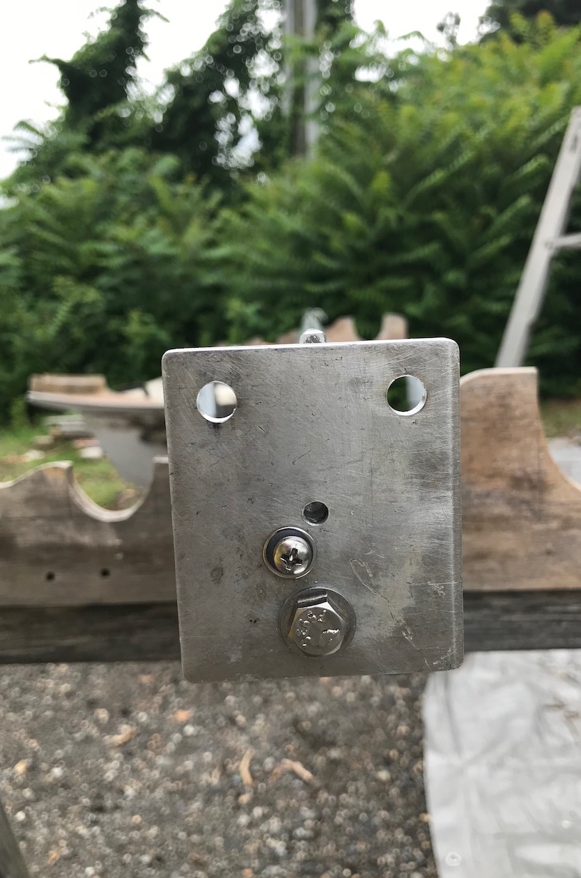
 In the case of Diana, the battery boxes being built in under the settee berths incurred a height-clearance problem - the Blue Sea fuse-block terminals would not fit under the (plywood) lid.  My solution was to fabricate, from copper bar stock, an extension featuring a 90-degree twist and to mount the fuse block on its side.

 The pic does not show the vent tube at the after end (left in the pic) of the battery box - this is to convey the hydrogen 'gas-off' out of the accommodation and back to a snorkel under the cockpit (remember: hydrogen rises; and the snorkel's height keeps water from getting in - which would flow straight onto the top of the battery).  The under-cockpit area is ventilated by a small solar-power exhaust vent in the Dorade box, which should, without sparks, carry this off without hassle.


My dad would certainly hate all this electrical complexity.  He once claimed, 'I'd have been happy with an extension cord thrown through a window!' (a notion which inspired me to wire the three 115VAC domestic-type outlets using the body of an actual 14/3 contractor/exterior-grade extension cord! - all connections sealed with tinned-copper heat-shrink terminals of course).  His Thoreau-like sense of simplicity can be stated, rather as that of Colin Chapman (Lotus Cars Ltd), as

Complexity + Expense + Weight = NOT SAILING.

But as I often remind him these days, Diana is not only a nicely-performing boat but a liveaboard home and working studio.  Unlike my dad, I like being on the boat for extended periods and would rather be on the boat under way than at any marina or mooring.  So for me the electrical system is rather mandatory.  Luckily I enjoy planning and assembling it.

- JC2


11 July 2021

Details details details

Mostly rigging details...

... at this time, as they're commemorated at the time of the mast stepping.

 Most of these will get some greater attention in further posts.  For now here's what's been done (and what's been taking all the time towards completion of the boat).

In no particular order.... 


Fish plate

 For split backstay - this is a pair of standard Schaefer parts but with an eye welded on each.   The lower eye can be used for hanging anything above the cockpit and the upper one can be used for belaying the upper flag halyard.


  Tang for inner forestay


 The wire stay is attached via 4:1 tackle to eye on foredeck.  The halyard (exit block below it) can be used as a pole lift.

 That red-white-blue line is genuine c.1980s-spec 5/16" Sampson XLS Yacht Braid, for the pole lift/inner-jib halyard.

The red & white line is the spinnaker halyard; the block (like some fairleads farther down) contains the down-side of the halyard on its way to a turning block at the mast step.

 Note cotter pins wrapped correctly with rigging/electrical tape.  These should never be left uncovered and never be fitted with only cotter rings (especially 20 feet above deck).

 Blue tape on tang was for identifying which wire goes where; I decided to leave it on to see how long it'd last!


 Lucky mast-step coin

 Ttaped to mast step just prior to stepping the mast.  I saved a 1974 Kennedy half-dollar for this (had it since it was new) but mislaid it in moving house; so I ordered a 1974 Eisenhower silver dollar on eBay.  Paid $1.25.

 The coin is taped up to insulate the silver from the aluminum mast step to prevent corrosion. 


Shroud tangs

  This is a Dwyer part replacing the original pair of (flimsy) single tangs.

 Note clevis pin attaching spreaders, replacing (stupid idea of) large cotter pin.  The cotter pins have yet to be 'finally' bent in this picture - such things are always checked 100% before stepping.

 Spreaders are original 1" round tubing from 1974, painted with Brightside.


  Spreader boots


 These are from Plastimo - I had never used this type before; but they went on very well.  The thing to remember about installing spreader boots is to not spare the rigging tape.

 The yellow and blue Marlow 5- or 6-mm line is just awful for tying knots; and even properly-done whipping will work itself out against the toughness of the cordage coating.  These have been replaced with proper sailing cordage from Yale and Sampson (using the 'ancient Chinese method' after the mast was up - ask me about this if you like).


  Combination steaming light and foredeck downlight


 This is a very nice fixture but it makes no provision for attaching the wiring to that in the spar, and especially not in any waterproof context.  I discovered a short in one of these connections when all was tested prior to stepping the mast.  When the connections were remedied, no room remained for the wiring connections.  A fellow contractor in the yard suggested making these legs, which I cut out, drilled holes, and painted between 11 pm and midnight on the day before the crane was scheduled for stepping the mast.  I attached these using 3/16" pop-rivets first thing in the morning - worked great.

 Note the Racelite fairlead eye attached with pop rivets and nylon washers between the aluminum and the stainless steel.  This is to prevent corrosion, especially in places that won't get scrutinized very often on account of being 20 feet up.

 Note also that halyards on port are flecked red and halyards on starboard are flecked blue (since they had no green in stock).  Principal halyards are all Yale UULS (discontinued; replaced in the market by 'ULS') which I prefer, even over (new-spec) Sampson XLS3.  It is a very high-quality line with a very soft hand.  And it has less susceptibility to kinking and hockling plus higher strength and lower stretch stats than the ubiquitous (for reasons that can be only down to marketing) NER Sta-Set X.


 Top end of trysail track

 Here is the track stop I made using StarBoard and two (mismatched) screws.  I will often make stuff like this using StarBoard (about the only kind of StarBoard application I would rely on).  The track is attached with pop-rivets through white electrical tape stuck to its back to insulate the stainless from the aluminum - a trick Capt Mike Lawrence and I used when we rerigged the Cherubini 48 schooner Amazing Grace/Light Reign together.

 The stainless-steel slides are just sitting there for comparison in this pic.  When the mast got stepped they all slid down to where they should be.

The shroud in the picture is the inner forestay, near its top end.


 Upper end of mast

Pic is prior to paint and attachment of fittings and masthead plate.


 Vent holes


 Yes; they do resemble the 'portholes' of a 1950s Buick!  These are 1-1/8" stainless-steel through-holes installed port-and-starboard in the topsides to provide fresh air to the holding tank (after pair), rode locker (next-forward pair), and forepeak above V-berth (forward pair).  These work really well, especially when wind is off the bow or on the beam.  The flow is small but steady - keeps off the musty smell.

 The foam stuck in the toilet-tank vent was to keep bugs out till the hoses were connected to the tank.  The rode-locker and forepeak vents have aluminum screen at the inner ends of the through-hulls to keep bugs from invading the interior (in my experience nylon screen will disintegrate or be eaten quite early).


Boom, as modified


 Diana's customized (original) boom, prior to painting.  The end was cut off at a stylish angle (1970s style, that is).  It also provides access for maintaining or removing the internal outhaul tackle.  The end fitting was fashioned from the original boom-end casting and furnished with a (custom-made) plate to carry the shackles for the topping lift and the reef line.


 Upper end of mast

 Showing spinnaker-halyard attachment ring on the (custom) masthead plate.  Clevis pin just below is for headsail-halyard sheaves.

 Jib and main have double halyards, to facilitate sail-setting options as well as for safety in redundancy.  I don't think I'd last two day-sails owning a boat without double halyards.  I've even had actual nightmares about losing a mainsail halyard right before rounding a key mark at the verge of a very ugly lee shore.


 Foot end of mast

 Showing what looks like a mass of wire and cordage.  This is how to prepare a mast for stepping.  Remember that, once up there, tangles and other mistakes threaten to have permanent effect - unless you don't mind hiring back the crane to send yourself up there or to bring the mast back down.

 The strangely cool part is that I truly won't need these (aged) sawhorses again for another half a decade now.


Masthead tricolor light fixture


 Custom-made by yours truly.  All of the commercially-available tricolor lights have two major drawbacks for this application:

1. They are all just TOO BIG.  The smallest one I found was like 3-1/4" in diameter.  There just is not enough real estate at the masthead of a boat under 30 feet for something like that.
 Consequently they're also very expensive (that Nautos 3-1/4" one was $125.  The Aqua Signal ones are upwards of $300).

2. They all have the running light atop the anchor light.  The anchor light is supposed to be an all-around light - that means not interrupted by two wires going past the bulb (as for the tricolor above it).  Also, I consider it more vital that they see you when you're at anchor (and likely asleep or not on board) than that they see you when you're under way (and on watch, to steer the boat actively to avoid any near-misses).  So the anchor light should always have been on top (and it's easier to run the wires that way; so the other makers have no excuse).

 This little innovation here solves both those problems.

 It was more difficult to assemble than I expected; but making the lenses and getting it to work were no trouble at all.  The pin on top was supposed to be finished with a little brass angel finial (cute but also fitting); but no-one would ship one in time.  Even without, it will still deter the birds from landing on it (and I left off the cap nut to help); and the Windex vane on the antenna (fitted to the masthead fitting) will scare them off as well.

 Of course you know that the anchor light and running lights should never been activated at the same time (this is not a motorboat!); this was just to test the spar wiring. Needless to say these are both fitted with appropriate LEDs.


Deck reinforcement

 Showing the aluminum angle used to reinforce the inner-forestay deck plate - the angle wanted a little tweaking.

 As a quick observation - it's not everyone who gets to use a 1970s stainless-steel mizzen-shroud chainplate from a Cherubini 44 as an anvil!


More (with detail) shall follow.  Stay tuned -

- JC2


29 May 2021

The Heat is On

Late May 2021

What various things have happened! - it taxes the mind (as my dad would say) to even begin to describe this long strange trip.  Some weird combination of government subsidies, native frugality, the determination of one rapidly growing 'too old' to do what he has too long only meant to do, the love and support of lifelong friends, and the reflection gained from performing COVID-related charity work has manifested all of this - and more - into a degree of progress as-yet unforeseen in the history of this (very protracted) project.  And we have the support of several very gracious donors to the cause to thank as well.

And, so, here we are.

Funnily, Diana has never been physically closer to the water since she was moved up from the NJ Shore to begin this very long, extensive, rather expensive, and impassioned restoration operation.  In this picture from 14 May 2021 she is sitting just to the other side of Brian's Chapparal and across about 40 feet of picnic area from the Delaware River, a hundred yards from where her predecessor (my dad's Hunter 25 'Cacciatrice', whose hull was barely 4-5 weeks newer) was launched in spring 1974.  Diana remains the inheritor of that legacy (even bearing Cacciatrice's original stainless-steel mainsheet blocks) even while she is very much something very different entirely - essentially 90-95% an all-new boat.

I keep having to explain to boatyard skeptics that this isn't boat-polishing, which most boat owners consider of paramount importance around here.  It's boat-building, which is an entirely different thing, which most of them, sadly, do not comprehend.  


The wealth of components acquired since June 2020 reads almost like a whole bill of materials for building a boat from scratch:

  • Topside paint, detail paint, bottom paint, boottop paint, interior paint, nonskid paint, epoxy, fiberglass resin, cushions, plywood, timber (mostly mahogany), varnish, sealer, sealants and bedding compounds, aluminum tubing, fasteners, much yacht hardware;
  • TWO fiberglass dinghies (one of which shall be listed for sale after some minor repairs);
  • Custom-ordered mainsail, new 135 genoa, small inner staysail to be flown from pole lift on foredeck, plus a never-used 1973 genoa - from an Essex 26! (perfect as a 150 genny for this boat);
  • GPS, depthfinder, stereo and speakers, cabin fans, many lights and components with which to restore the original ones, marine wire, heat-shrink wire ends, LED bulbs for nearly everything;
  • Remote-control kit for outboard motor;
  • SS folding boarding ladder, customized for transom;
  • Flexible water tanks, inline particle filters, galley faucet (completely custom), fresh-water hose;
  • Evacuation pump for holding tank (replacing earlier one which was good only as bilge pump);
  • Custom lifeline stanchions (8);
  • Components for fabricating custom masthead tricolor light and custom-fitting steaming light;
  • Much sailboat and deck hardware including several more (used, period-correct) chrome Lewmar winches;
  • Genuine 1980s new-old-stock Simpson-Lawrence (NOT Lewmar!) Delta 14-lb primary anchor, two forward anchor rodes, each with over 20 ft of chain and 200 ft of 8-plait line;
  • Half a dozen of what will be a wardrobe of about 18 flags, for various purposes, carried in flag locker.


Detailed blog entries will highlight each of these; but the following are all major developments since she went under Shrinkwrap in December 2018:

  • Boat moved from the most expensive marina on the Delaware River to Burlington NJ, June 2020;
  • Shrinkwrap peeled off, water-saturation damage identified and remedied, hull repainted;
  • Motor sent out for rebuilding;
  • Mast repainted, rebuilt with new hardware, halyards reeved through spar(s);
  • Replacement cabin windows (properly called 'deadlights') installed using Life Seal, resolving matter of leaks;
  • Port and starboard anchor-rode lockers constructed under V-berth (far aft and down low for seaworthy weight distribution);
  • Much electrical wiring, components and circuitry installed and/or revamped;
  • Much custom splicing of cordage including control lines, mainsheet and traveler, backstay adjuster;
  • Much paint applied to topsides (hull), deck, cockpit, interior; 
  • Unbelievable amount of mahogany cabinetry and trim varnished or revarnished, inside and out;
  • Motor mount dismantled, rebuilt, reinstalled on transom;
  • Boarding ladder installed on transom, not as designed (this involved lots of redesign effort);
  • Topsides received final coat of white Brightside;
  • Graphics artwork realized as high-quality appliques;
  • Hull graphics including waterline stripe painted on, and custom logo appliques applied;
  • All standing rigging and spar fixtures finalized;
  • Mast stepped, rigging (preliminarily) tuned;
  • Lifeline stanchions installed, awaiting final lifeline rigging;
  • Traveler mounted with ball-bearing car and Cacciatrice's original 1974 Schaefer fiddle blocks attached;
  • Most of the navigation instruments installed;
  • Motor rebuild completed, motor sent back in for fitment of remote controls;
  • Solar-array rack designed, preliminarily assembled;
  • Original ash-mahogany tiller stripped, coated in epoxy, varnished;
  • Custom rudder-shaft collar fabricated, installed;
  • Original motor bracket repaired with welding and new hardware;
  • Mahogany foredeck hatch repaired after winter(s) storage and revarnished;
  • Bunk cushions and backrests custom-shaped, sent off to specialist for completion;
  • All contact with regional custom-railing fabricators terminated due to lack of interest on their part, so scavenged pulpit (from another junked boat, since stored in attic) will have to do (actually fits really well);
  • US 50-star flag begins being flown of mainmast halyard every day skipper is present, in anticipation of launch within first two weeks of June.


Progress continues apace, with a surprisingly little bit of important things left before boat can safely and conveniently go into the water.  What remains:

  • Application of additional barrier coat, including sanding off the 'overflow' of white paint under the stripe;
  • Application of 'final' white and cream deck paint;
  • Fitment of winches and cleats (waiting on above); 
  • Completion of freshwater-service system, installation of tanks - and one connection in the holding-tank overboard-discharge system;
  • Fitting and installing of little Dorade boxes at the forward corners of the hatch hood; and the hatch-hood trim that can only be done when the boxes are done (this has been rather annoying for me but they'll look terrific);
  • Fabrication of fiberglass shell for mounting GPS screen; 
  • Mounting stereo and speakers (mainly stereo, for some reason never got round to it;
  • Mounting TV, after making a pretty mahogany frame for it;
  • Fabrication of double-leafed cabin table, to include hideaway compartment for laptop computer;
  • Molding of fiberglass icebox/refrigerator bin, fitment of drains, completion of surrounding woodwork (I keep forgetting to do this!);
  • Fitment of mahogany deck handrails (which are just like what my dad designed, not like the simple teak stick Hunter supplied);
  • Installation of outboard motor and its associated fuel line, electric wiring, throttle and shift cables, and after that the fuel tank can go back in;
  • Mounting of pulpit;
  • Fabrication of dodger frame over companionway hatch (this can be covered later, though this is summer now and sooner works fine too!);
  • Final assembly of solar-array rack, after which lifelines can be cut and installed;
  • Riddling-out of dinghy-towing bridle and stern-anchor tackle;
  • Cheek blocks, halyard stoppers and winches installed for deck lines;
  • Acquisition of the rest of the flags, including state courtesy flags, a few necessary code flags, and ordering the custom family-crest and personal-ensign flags;
  • Good overall cleaning of everything and application of StarBrite UV-barrier PTEF polish (no compound!);
  • Launch, commissioning, shakedowns, christening ceremony and party.


In related developments, I 'jumped off the bridge' - made a commitment - regarding the apartment, which I shall vacate for good by the end of June 2021, when I will have to have relocated semi-permanently aboard.  Select furniture, books and housewares go into storage; the guitars, family artwork, electronics and my dad's drawings archive shall go into a (to-remain-undisclosed) climate-controlled vault, awaiting some point in future when I may return for that stuff... or not, as events may develop.


This blog, originally dedicated to the restoration work, shall continue with detailed information about the boat itself - keep it bookmarked to see further updates of the progressing developments and intimate views of the boat as she shall turn out.


As ever, all encouragement, support, and positive vibes are appreciated!


* * *